One 20h.p. 415 volt 3 phase Induction. Wired with 7/.064 cables
Two 15h.p. 415 volt 3 phase Induction. Wired with 7/.052 cables
Three 10h.p. 415 volt 3 phase Induction. Wired with 19/.052 cables
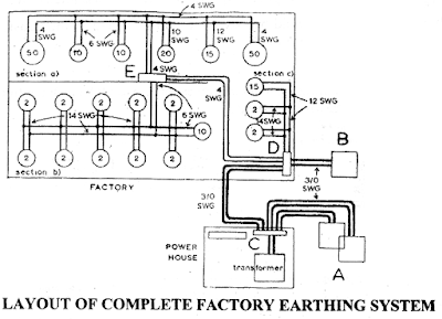
Twelve 2h.p. 415 volt 3 phase Induction. Wired with 71.036 cables Transformer 250 kVA 3 phase 11000/400 volt Neutral to be earthed on the premises: Cables on L.T. side are 37/.083. Water Level Approximately 30 ft. down Solution The largest possible source of fault current is the transformer, and so at least one of the earthing plates will have to be as near as possible to it. A convenient site is found at position A. Since the water level is about 30 ft. down, two earthing plates can be installed in the same excavation 30 ft. down, in order to save money and time digging two holes 30 ft. deep. For extra safety, an additional plate must be installed and a convenient place some distance away is found at B. This plate should be installed about 12 ft. down and provision made for keeping it damp by regular watering. One connecting point is made at C near the main switch-board, another at D, and the third at E, positioned underneath the combination switchfuse board, just above the cable ducting. These connecting points are then joined by wires run in the cable ducts. Since this example deals entirely with the earthing of electrical apparatus, then two separate earth continuity conductors are run throughout the factory. (The earth continuity conductors to other metal work i.e., distribution fuse boards, switchfuse, etc, have not been shown for clarity).
Having determined the location of plates and connection points, the sizes of earth continuity conductors and earthing leads have to be found. From Table 30, the appropriate size of earth conductor can be found opposite each cable size.
Earth continuity conductor to 50h.p motor (191.064 cables) = 4 SWG
Earth continuity conductor to 20h.p motor (71.064 cables) = 10 SWG
Earth continuity conductor to 15h.p motor (71.052 cables) = 12 SWG
Earth continuity conductor to 10h.p motor (191.052 cables) = 6 SWG
In this section, the largest size of motor is 50h.p. and so the main pair of earth continuity conductors must be capable of carrying any fault current produced by either of these two motors. Since each 50h.p. motor is at the far end of the distribution in this section then the two earth continuity conductors running around this section must each be 4 S.W.G. The earth continuity conductors from the smaller motors to the main pair are as listed.
Earth continuity conductors to 10h.p. motor (19/.052 cables) 6 SWG
Earth continuity conductors to 2h.p. motor (71.036 cables) = 14 SWG
This distribution system in this section is such that the pairs connecting point at E are each 6 S.W.G. but 14 S.W.G. to each of 2h.p. motors. This then provides a safe path if a fault occurs on the 10h.p. motor.
Earth continuity conductor to 15h.p. motor (71.052 cables) = 12 S.W.G.
Earth continuity conductor to 2h.p. motor (71.036 cables) = 14 S.W.G.
The pair of main earth continuity conductors from the 1 5h.p. motor to the connecting point at D are each 12 S.W.G. but 14 S.W.G. from each of the 2h.p. motors. The size of the earthing leads can now be determined. Since the cables on the L.T. side of the transformer are 37/.083, then from Table 30, either 3/0 S.W.G. copper wire, or in x in. or 1 in. x fin, copper strip can be used. It is assumed that 3/0 S.W.G. wire is easily available, so this would be used. If a fault did occur in the transformer, the fault current would flow to the earth plates.
Generally an earthing system comprises three parts the earth continuity conductor, the earthing lead and the earth electrode.


No comments:
Post a Comment