(i) Armature resistance control.
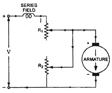
(ii) Shunted armature control and.
(iii) Armature terminal voltage control. 1. Armature Resistance Control This is the most common method employed. It is obtained in the same way as for a dc shunt motor with the exception that the control resistance may be connected directly in series with the supply to the complete motor. Control of armature voltage for the series motor is the same as the voltage applied to the complete motor. The drawbacks of armature resistance control for machines with shunt fields are not as important in the speed .control of dc series motors.
The poor speed regulation that is inherent in this method has no significance for the control of dc series motors, since the speed characteristic of a dc series motor is a rapidly dropping curve. The power loss in the control resistance for many applications of dc series motors is not too serious, since in these applications the control is utilized for a large portion of time for reducing the speed under light-load conditions and is only employed intermittently when the motor is carrying full-load. The speed-torque characteristics of dc series motors with resistance control. The maximum range of speed controls of about will be available depending on the load. This method of speed control is most economical for constant torque drives. This method of speed control is employed chiefly for dc series motors driving cranes, hoists, trains etc. because such drives operate on intermittent duty.

For satisfactory operation under violently changing loads, the diverting resistance should be highly inductive because it is connected across the series field winding which normally has very low resistance. If the field winding is shunted by means of non inductive resistance, any sudden change in the load current will not immediately affect the field winding owing to the high inductance of the field circuit impeding any violent change in its current.


The machines are started up in series with each other and a starting or control resistance as illustrated.
a. The additional resistance is gradually cut-out by the controller as the motors attain speeds and finally the control resistance is totally removed, then each motor has one half of the line voltage across it.
(b). This is the first running position. In this position for may given value of armature current, each motor will run at half of its normal speed. Since there is no external resistance in the circuit, there is no waste of energy and so motors operate at an efficiency nearly equal to that obtainable with full line voltage across the terminal of each motor.
(c) When it is desired to increase the speed of the combination, two motors are connected in parallel and in series with a variable resistant R.
This resistance is gradually cut out as the motors attain the speed and finally when this resistance is totally removed from the circuit, as illustrated.
(d) The second running position is obtained. In this position each motor is connected across the full line voltage.

No comments:
Post a Comment